Consulting phone:
135-3037-2041
(Mr.Wang)
Product introduction:
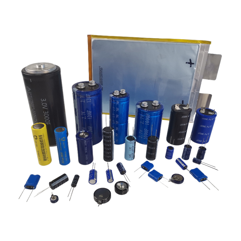
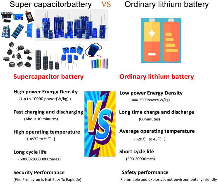
Gold capacitor battery is also called super capacitor and farad capacitor. It stores energy through polarized electrolyte and belongs to a kind of double-layer capacitor. Because there is no chemical reaction in the process of energy storage, the process of energy storage is reversible. It is precisely because this supercapacitor can charge and discharge hundreds of thousands of times repeatedly. Supercapacitors generally use activated carbon electrode materials, which have the characteristics of large adsorption area and large electrostatic storage, and are widely used in new energy vehicles.
Series Specification Sheet:
series name | series | |||||||
type name | YKY-2R7 | |||||||
Rated voltage VR | 2.7V | |||||||
surge voltage | 2.85V | |||||||
Capacity range | 120F-3000F | |||||||
Operating temperature range | -40℃~+85℃ | |||||||
Product life | Normal temperature cycle life: 25°C, 500,000 cycles between VR and 1/2VR , capacity decay ≤30%, internal resistance change ≤4 times | |||||||
High temperature endurance life: 85℃, keep VR , 1000 hours, capacity decay ≤30%, internal resistance change ≤4 times | ||||||||
Product performance table:
| model | Voltage V | Capacity F | AC internal resistance mΩ1KHz | 24h leakage current uA | Product size mm | ||
| Diameter D | length H | Pitch P | |||||
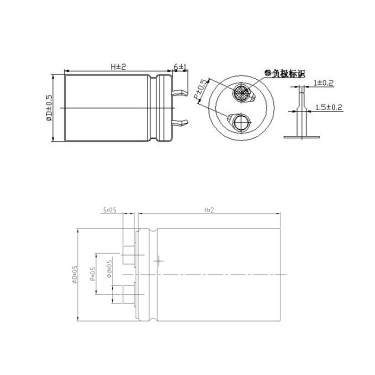
YKY-2R7-J127VYJ28 | 2.7 | 120 | 15 | 1200 | 22 | 46 | 10 |
YKY-2R7-J157VYJ29 | 2.7 | 150 | 15 | 1500 | 25.4 | 40 | 10 |
YKY-2R7-J207VYJ33 | 2.7 | 200 | 10 | 2000 | 35 | 61 | 10 |
YKY-2R7-J207VYJ31 | 2.7 | 200 | 10 | 2000 | 35 | 61 | 10 |
YKY-2R7-J207VYJ30 | 2.7 | 200 | 10 | 2000 | 25.4 | 54 | 10 |
YKY-2R7-J227VYJ31 | 2.7 | 220 | 10 | 2200 | 30 | 50 | 10 |
YKY-2R7-J227VYJ33 | 2.7 | 220 | 10 | 2200 | 35 | 61 | 10 |
YKY-2R7-J307VYJ32 | 2.7 | 300 | 10 | 3000 | 35 | 54 | 10 |
YKY-2R7-J307VYJ31 | 2.7 | 300 | 10 | 3000 | 30 | 50 | 10 |
YKY-2R7-J407VYJ33 | 2.7 | 400 | 10 | 4000 | 35 | 61 | 10 |
YKY-2R7-J477UNJ34 | 2.7 | 470 | 5 | 4700 | 35 | 96 | 10 |
YKY-2R7-J707UNJ34 | 2.7 | 700 | 5 | 6500 | 35 | 96 | 12.7 |
YKY-2R7-J108UNJ71 | 2.7 | 1000 | 5 | 10000 | 51 | 71 | 21.8 |
YKY-2R7-J128UNJ49 | 2.7 | 1200 | 3 | 12000 | 51 | 108 | 21.8 |
YKY-2R7-J158UNJ49 | 2.7 | 1500 | 3 | 15000 | 51 | 108 | 21.8 |
YKY-2R7-J208UNJ50 | 2.7 | 2000 | 2 | 20000 | 51 | 133 | 21.8 |
YKY-2R7-J308UNJ52 | 2.7 | 3000 | 2 | 30000 | 64 | 133 | 28.2 |
Product Size:

product application:
1) Portable equipment: notebook computer, video camera, PDA, digital camera, portable DVD, etc
2) Household appliances: two-way radios, walkie talkies, electric toys, electric bicycles, emergency lighting
3) Military equipment
4) Medical treatment
5) Electric tools

testing method:
capacity
1 Constant current discharge method
(1) Measurement circuit
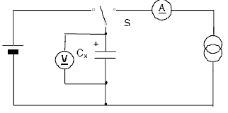
Figure 1 - Constant Current Discharge Method Circuit
2 Measurement method
◎ The DC voltage of the constant current/constant voltage source is set to the rated voltage (UR ) .
◎ Set the constant current value of the constant current charging and discharging device specified in Table 1.
◎ Switch the switch S to the DC power supply, and charge it with constant voltage for 30 minutes after the constant current/constant voltage source reaches the rated voltage.
◎ After charging, switch the switch S to a constant current discharge device to discharge with a constant current.
◎ Measure the time t1 and t2 of the voltage across the capacitor from U1 to U2, as shown in Figure 2, and calculate the capacitance value according to the following equation :
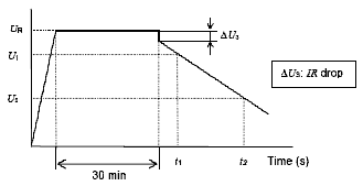
Figure 2 Terminal voltage characteristics of capacitors

in
C capacity (F);
I discharge current (A);
U1 measures the initial voltage (V) ;
U 2 measures the termination voltage (V);
t 1 Time (s) for the discharge voltage to reach U1;
t 2 Time (s) for the discharge voltage to reach U2.
See Table 1 for the discharge current I and the voltages U1 and U2 at which the discharge voltage drops .
3 Equipment: A, ARBIN supercapacitor test system B, linear DC stabilized power supply C, constant current discharge device D, voltage recorder
Internal resistance
Test method: AC impedance method
Measurement circuit
The measurement circuit shown is tested.
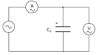
Figure 3 - AC Impedance Method Circuit
Measurement methods
The internal resistance Ra of the capacitor should be calculated by the following formula:

in
Ra AC internal resistance (Ω);
U RMS value of AC voltage (V rms);
I AC current rms value (V rms).
The frequency at which the voltage is measured, should be 1kHz.
The AC current should be 1mA to 10mA.
使用事项:
超级电容器不可使用在如下状态:
1) 超过标称温度的温度
当电容器温度超过标称温度时,将会导致电解液分解,同时电容器会发热,容量下降,
而且内阻增加,寿命缩短。
2) 超过额定电压的电压
当电容器电压超过标称电压时,将会导致电解液分解,同时电容器会发热,容量下降,
而且内阻增加,寿命缩短。所以降低使用电压可提高使用寿命。
3) 逆电压或交流电压的加载
1.周围温度对超级电容器的影响
超级电容器的使用寿命受使用温度的影响,一般情况下,使用温度提升10℃,超级电容器的寿命会缩短一半,请尽量在低于最高使用温度的低温环境下使用。超过最高使用温度使用的话,可能会造成特性急剧劣化,破损。
超级电容器的使用温度不仅要确认设备周围温度,内部温度,还要确认设备内发热体(功率晶体管、电阻等)的放射热,纹波电流引起的自行发热温度。此外,还请勿将发热体安装在超级电容器的附近。
2.请按电容器的正负极标识正确使用。
3.请避免在以下环境中使用超级电容器。
a) 直接溅水、盐水及油的环境、或处于结露状态、充满着气体状的油分或盐分的环境。
b) 充满着有害气体(硫化氢、亚硫酸、氯、氨、溴、溴化甲基等)的环境。
c) 溅上酸性及碱性溶剂的环境。
d) 阳光直射或有粉尘的环境。
e) 遭受过度的振动及冲击的环境。
4.在焊接过程中要避免使电容器过热(1.6mm的印刷线路板,焊接时应为260℃,时间不超过5s)。
5.请避免在超级电容器的引出极间或连接板焊点间进行电路配线。
6.过电压及超过工作温度范围等超出额定条件使用时,可能导致压力阀动作,电解液会喷出。因此,请采用已考虑到此异常状况可能发生的设计方法。
7.快速充放电时,充电开始时、放电开始时,会产生由内部阻抗导致的压降(也叫IR降),所以,请采用已考虑到电压变化幅度的设计方法。
8.功率型大容量产品(约10F以上产品)充电状态下如果端子短路,会有数百安培的电流流过,危险。请不要在充电状态下进行安装和拆卸。
9.不要把电容器放入已溶解的焊锡中,只在电容器的导针上粘焊锡。不可让焊接用焊棒接触电容器热缩管。
10.安装后,不可强行扭动或倾斜电容器。
11.超级电容器串联使用时,存在单体间的电压均衡问题。