Consulting phone:
135-3037-2041
(Mr.Wang)
Product introduction:
The double-layer capacitance is a new kind of capacitor based on the theory of interface double-layer proposed by German physicist Helmholtz. It is well known that the surface of the metal electrode inserted into the electrolyte solution and both sides of the liquid surface will have excess charges with opposite signs, which will cause potential difference between the phases. Then, if two electrodes are inserted in the electrolyte at the same time and a voltage less than the decomposition voltage of the electrolyte solution is applied between them, then the positive and negative ions in the electrolyte will rapidly move towards the two poles under the action of the electric field, and form a close charge layer on the surface of the two electrodes, namely the double electric layer, which forms a double electric layer similar to the polarization charge generated by the dielectric in the traditional capacitor under the action of the electric field, Thus, the capacitance effect is produced. The compact electric double layer is similar to the flat capacitor. However, because the close charge layer spacing is much smaller than the distance between the charge layers of the ordinary capacitor, it has a larger capacitance than the ordinary electric double layer.
Series specification table:
Specification | characteristic | |||||||
Rated voltage VR | 3.0V.DC | |||||||
surge voltage | 3.15V.DC | |||||||
Capacity range | 1F-120F | |||||||
Operating temperature range | -40℃~+65℃ | |||||||
Product life | Normal temperature cycle life: At 25°C, the capacitor is charged and discharged 1 million times between the specification voltage and the half rated voltage with a constant current. Capacity attenuation ≤30% times, internal resistance change ≤3 times | |||||||
High temperature endurance life: under the condition of +65℃, the rated voltage is applied for 1000 hours. Capacity attenuation 30%, internal resistance change ≤3 times | ||||||||
Product performance table:
Product number | Rated voltage (V) | Nominal capacity (F) | Product size mm | Internal resistance | Working current (A)∆ T=15℃ | Peak current (A) | Leakage current (72hrs/µA) | High energy (Wh) | Energy density (Wh/kg) | functional density (kw/kg) | |
Outer diameter (ϕD) | Height (L) | ESRA C(mΩ/1KHz) | |||||||||
YKY3R0S105C01DSZ | 3.0 | 1 | 6.3 | 12 | 250 | 0.18 | 0.68 | 3 | 0.0013 | 1.67 | 1.20 |
YKY3R0S105C02DSZ | 3.0 | 1 | 8 | 12 | 180 | 0.26 | 0.83 | 5 | 0.0013 | 1.37 | 1.48 |
YKY3R0S205C02DSZ | 3.0 | 2 | 8 | 12 | 130 | 0.26 | 1.15 | 6 | 0.0025 | 2.75 | 1.48 |
YKY3R0S205C03DSZ | 3.0 | 2 | 8 | 16 | 120 | 0.43 | 1.74 | 8 | 0.0025 | 2.27 | 2.73 |
YKY3R0S335C04DSZ | 3.0 | 3.3 | 8 | 20 | 95 | 0.53 | 2.53 | 10 | 0.0041 | 2.84 | 2.57 |
YKY3R0S505C04DSZ | 3.0 | 5 | 8 | 20 | 80 | 0.59 | 3.41 | 12 | 0.0063 | 4.17 | 3.00 |
YKY3R0S505C06DSZ | 3.0 | 5 | 10 | 20 | 70 | 0.77 | 3.93 | 15 | 0.0063 | 2.84 | 2.73 |
YKY3R0V705C05DSZ | 3.0 | 7 | 8 | 25 | 80 | 0.71 | 4.38 | 18 | 0.0088 | 4.61 | 2.84 |
YKY3R0V705C06DSZ | 3.0 | 7 | 10 | 20 | 60 | 0.81 | 4.95 | 18 | 0.0088 | 3.65 | 2.81 |
YKY3R0V106C06DSZ | 3.0 | 10 | 10 | 20 | 50 | 0.94 | 6.82 | 18 | 0.0125 | 5.1 | 3.67 |
YKY3R0V106C07DSZ | 3.0 | 10 | 10 | 25 | 40 | 1.27 | 8.33 | 20 | 0.0125 | 4.46 | 2.84 |
YKY3R0V106C09DSZ | 3.0 | 10 | 12.5 | 20 | 40 | 1.35 | 8.57 | 25 | 0.0125 | 3.57 | 4.11 |
YKY3R0V156C09DSZ | 3.0 | 15 | 12.5 | 20 | 40 | 1.35 | 10.59 | 30 | 0.0188 | 5.07 | 3.89 |
YKY3R0V156C10DSZ | 3.0 | 15 | 12.5 | 25 | 35 | 1.54 | 10.98 | 35 | 0.0188 | 4.36 | 3.59 |
YKY3R0V206C10DSZ | 3.0 | 20 | 12.5 | 25 | 35 | 1.66 | 13.64 | 50 | 0.0250 | 5.43 | 3.91 |
YKY3R0V256C12DSZ | 3.0 | 25 | 16 | 20 | 25 | 1.9 | 16.67 | 70 | 0.0313 | 5.21 | 3.60 |
YKY3R0V306C14DSZ | 3.0 | 30 | 16 | 30 | 20 | 2.53 | 20.45 | 80 | 0.0375 | 4.46 | 3.21 |
YKY3R0V506C15DSZ | 3.0 | 50 | 18 | 40 | 15 | 4.34 | 37.5 | 100 | 0.0625 | 4.7 | 4.06 |
YKY3R0V107C16DSZ | 3.0 | 100 | 18 | 60 | 12 | 5.85 | 57.69 | 260 | 0.1250 | 5.95 | 3.21 |
YKY3R0V107C17DSZ | 3.0 | 120 | 18 | 60 | 12 | 5.85 | 61.64 | 260 | 0.1500 | 7.14 | 3.21 |
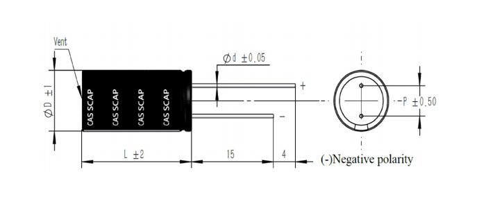
Dimensions (unit: mm)

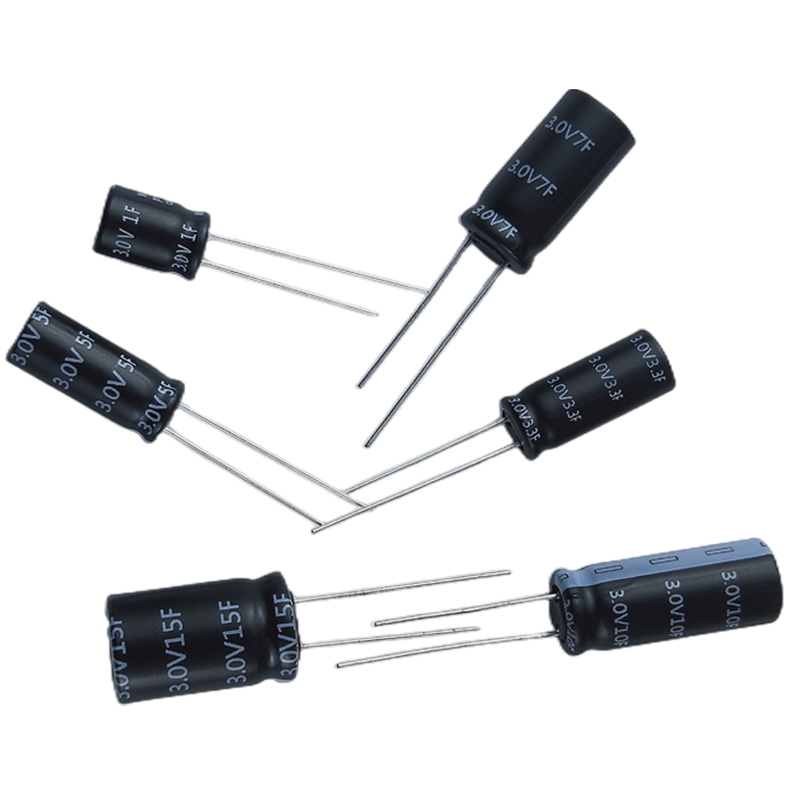
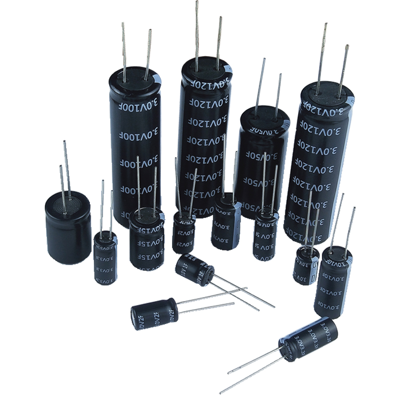
Product display:


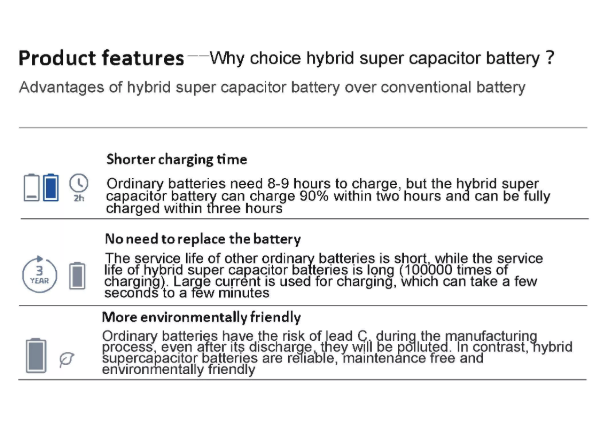
Product advantages:

Application areas:
![1669272893126405.png [~]P`CO9T}7YQI[(0(}~%%E.png](http://en.szsyky.cn/data/upload/202211/1669272893126405.png)
testing method:
1. Electrostatic capacity test method:
(1) Test principle
The test of the electrostatic capacity of the supercapacitor is to use the method of constant current discharge of the capacitor, and calculate it according to the formula.
C=It(U1-U2)
In the formula: C - electrostatic capacity, F;
I-constant discharge current, A;
U1, U2 - use voltage, V;
t-Discharge time required for U1 to U2, S
(2), test procedure
Charge the capacitor with a current of 100A, charge the capacitor to the working voltage and keep the voltage constant for 10 seconds, then discharge the capacitor with a current of 100A, take U1 as 1.2V and U2 as 1.0V, record the discharge time within this voltage range, and the total cycle Capacitance, take the average value.
2. Stored energy test
(1) Test principle:
The test of supercapacitor energy is carried out by the method of discharging the capacitor with constant power to 1/2 of the working voltage with a given voltage range of the capacitor. The output energy W of the capacitor is obtained from the relationship between the constant discharge power P and the discharge time T, namely:
W=PT
(2) Test procedure
Charge the capacitor to the working voltage with a constant current of 100A, and then keep it constant until the charging current drops to the specified current (10A for traction type, 1A for start-up type), after 5 seconds of rest, discharge the capacitor with constant power to 1/2 of the working voltage, record Discharge time and calculate magnitude. Repeat the measurement 3 times and take the average value.
3. Equivalent series resistance test (DC)
(1) Test principle
The internal resistance of the capacitor is measured according to the sudden change of the voltage within 10 milliseconds of the capacitor disconnecting the constant current charging circuit. That is: in the formula:
R - the internal resistance of the capacitor;
U0 - capacitor cut off the voltage before charging;
Ui - cut off the voltage within 10ms after charging;
I - cut off the current before charging.
(2) Measurement process
Charge the capacitor with a constant current of 100A, disconnect the charging circuit when the charging working voltage is 80%, use a sampling machine to record the voltage change value within 10 milliseconds after the capacitor is powered off, and calculate the internal resistance, repeat 3 times, and take the average value.
4. Leakage current test
After charging the capacitor to the rated voltage with a constant current of 100A, charge the capacitor with a constant voltage for 30min at this voltage value, and then leave it open for 72h. During the first three hours, the voltage value was recorded every minute, and during the remaining time, the voltage value was recorded every ten minutes.
Calculate the self-discharge energy loss, SDLF=1-(V/VW)2, and the calculation time points are: 0.5, 1, 8, 24, 36, 72h.
Note: The voltage tester must have high input impedance to minimize the impact of discharge.