Consulting phone:
135-3037-2041
(Mr.Wang)
Product introduction:
Faraday gold capacitor: It is produced by the charge confrontation caused by the directional arrangement of electrons or ions at the electrode/solution interface. For an electrode/solution system, a double electric layer will be formed at the interface between the electron-conducting electrode and the ionic conducting electrolyte solution. When an electric field is applied to the two electrodes, the anions and cations in the solution migrate to the positive and negative electrodes respectively, forming a double electric layer on the surface of the electrode; After removing the electric field, the positive and negative charges on the electrode attract the opposite charge ions in the solution, which makes the double electric layer stable, and generates a relatively stable potential difference between the positive and negative electrodes. At this time, for a certain electrode, it will generate the same amount of anisotropic ionic charge as the charge on the electrode within a certain distance (the dispersion layer) to keep it neutral; When the two poles are connected to the external circuit, the charge on the electrode migrates to generate current in the external circuit, and the ions in the solution migrate to the solution to be electrically neutral, which is the charge and discharge principle of the double-layer capacitor.
Series specification table:
series name | series | |||||||
type name | YKY-5R5 | |||||||
Rated voltage VR | 5.5V | |||||||
surge voltage | 5.8V | |||||||
Capacity range | 0.1F-1.5F | |||||||
Operating temperature range | -25℃~+70℃ | |||||||
Product life | Normal temperature cycle life: 25°C, 500,000 cycles between VR and 1/2VR , capacity decay ≤30%, internal resistance change ≤4 times | |||||||
High temperature endurance life: 75℃, keep VR , 1000 hours, capacity decay ≤30%, internal resistance change ≤4 times | ||||||||
Product performance table:
model | Voltage V | Capacity F | AC internal resistance Ω1KHz | 24h leakage current uA | Product size mm | |||
Diameter D | height H | Pitch P | ||||||
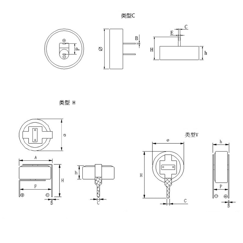
YKY-5R5-D104VYV3C | 5.5 | 0.1 | 50 | 0.8 | 13 | 6.5 | 5 | |
YKY-5R5-D104VYH3E | 5.5 | 0.1 | 50 | 0.8 | 11.5 | 6.4 | 10.5 | |
YKY-5R5-D104VYC3H | 5.5 | 0.1 | 50 | 0.8 | 11.5 | 12.3 | 4.7 | |
YKY-5R5-D224VYV3C | 5.5 | 0.22 | 40 | 1.76 | 13 | 6.5 | 5 | |
YKY-5R5-D224VYH3E | 5.5 | 0.22 | 40 | 1.76 | 11.5 | 6.4 | 10.5 | |
YKY-5R5-D224VYC3H | 5.5 | 0.22 | 40 | 1.76 | 11.5 | 12.3 | 4.7 | |
YKY-5R5-D334VYV3C | 5.5 | 0.33 | 40 | 2.64 | 13 | 6.5 | 5 | |
YKY-5R5-D334VYH3E | 5.5 | 0.33 | 40 | 2.64 | 11.5 | 6.4 | 10.5 | |
YKY-5R5-D334VYC3H | 5.5 | 0.33 | 40 | 2.64 | 11.5 | 12.3 | 4.7 | |
YKY-5R5-D474VYV3C | 5.5 | 0.47 | 40 | 3.76 | 13 | 6.5 | 5 | |
YKY-5R5-D474VYH3E | 5.5 | 0.47 | 40 | 3.76 | 11.5 | 6.4 | 10.5 | |
YKY-5R5-D474VYC3H | 5.5 | 0.47 | 40 | 3.76 | 11.5 | 12.3 | 4.7 | |
YKY-5R5-D684VYV3C | 5.5 | 0.68 | 15 | 8 | 20.5 | 7 | 6 | |
YKY-5R5-D684VYH3C | 5.5 | 0.68 | 15 | 8 | 20.5 | 7.4 | 5 | |
YKY-5R5-D684VYC3H | 5.5 | 0.68 | 15 | 8 | 18.7 | 5.5 | 20 | |
YKY-5R5-D105VYV3C | 5.5 | 1.0 | 10 | 8 | 18.7 | 20.2 | 5 | |
YKY-5R5-D105VYH3C | 5.5 | 1.0 | 10 | 8 | 20.5 | 7 | 6 | |
YKY-5R5-D105VYC3H | 5.5 | 1.0 | 10 | 8 | 20.5 | 7.4 | 5 | |
YKY-5R5-D155VYV3C | 5.5 | 1.5 | 10 | 12 | 18.7 | 20.2 | 5 | |
YKY-5R5-D155VYH3C | 5.5 | 1.5 | 10 | 12 | 18.7 | 5.5 | 20 | |
YKY-5R5-D155VYC3H | 5.5 | 1.5 | 10 | 12 | 20.5 | 7.4 | 5 | |
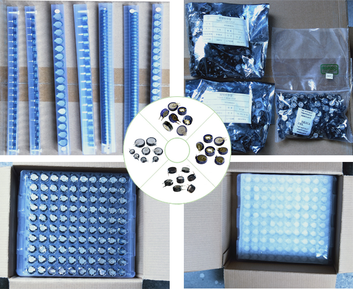
Product display:


Product Size:

Product use:

Product packaging:

Product application scope:
The pulse power performance, long service life and reliable operation in extreme temperature environment of supercapacitors are fully suitable for those applications requiring repetitive electric energy pulses in a fraction of a second to a few minutes, making them energy storage and power transmission solutions for transportation, renewable energy, industrial and consumer electronics and other applications, such as electric vehicles (EV/HEV), military Light rail, aviation, electric bicycles, backup power supply, power generation (wind power generation, solar power generation), communication, consumer and entertainment electronics, signal monitoring RAM, detonators, automobile recorders, intelligent instruments, vacuum switches, digital cameras, motor drives, intelligent three meters, UPS, security equipment, communication equipment, flashlights, water meters, gas meters, taillights, small household appliances and other fields have broad market prospects.
![1676603600159720.png @K}RO@}2GS}O7])T_TR)23R.png](http://en.szsyky.cn/data/upload/202302/1676603600159720.png)
Application areas:
testing method:
1. Electrostatic capacity test method:
(1) Test principle
The test of the electrostatic capacity of the supercapacitor is to use the method of constant current discharge of the capacitor , and calculate it according to the formula.
C=It(U1-U2)
In the formula: C - electrostatic capacity, F;
I-constant discharge current, A;
U1, U2 - use voltage, V;
t-Discharge time required for U1 to U2, S
(2), test procedure
Charge the capacitor with a current of 100A, charge the capacitor to the working voltage and keep the voltage constant for 10 seconds, then discharge the capacitor with a current of 100A, take U1 as 1.2V and U2 as 1.0V, record the discharge time within this voltage range, and the total cycle Capacitance, take the average value.
2. Stored energy test
(1) Test principle:
The test of supercapacitor energy is carried out by the method of discharging the capacitor with constant power to 1/2 of the working voltage with a given voltage range of the capacitor. The output energy W of the capacitor is obtained from the relationship between the constant discharge power P and the discharge time T, namely:
W=PT
(2) Test procedure
Charge the capacitor to the working voltage with a constant current of 100A, and then keep it constant until the charging current drops to the specified current (10A for traction type, 1A for start-up type), after 5 seconds of rest, discharge the capacitor with constant power to 1/2 of the working voltage, record Discharge time and calculate magnitude. Repeat the measurement 3 times and take the average value.
3. Equivalent series resistance test (DC)
(1) Test principle
The internal resistance of the capacitor is measured according to the sudden change of the voltage within 10 milliseconds of the capacitor disconnecting the constant current charging circuit. That is: in the formula:
R - the internal resistance of the capacitor;
U0 - capacitor cut off the voltage before charging;
Ui - cut off the voltage within 10ms after charging;
I - cut off the current before charging.
(2) Measurement process
Charge the capacitor with a constant current of 100A, disconnect the charging circuit when the charging working voltage is 80%, use a sampling machine to record the voltage change value within 10 milliseconds after the capacitor is powered off, and calculate the internal resistance, repeat 3 times, and take the average value.
4. Leakage current test
After charging the capacitor to the rated voltage with a constant current of 100A, charge the capacitor with a constant voltage for 30min at this voltage value, and then leave it open for 72h. During the first three hours, the voltage value was recorded every minute, and during the remaining time, the voltage value was recorded every ten minutes.
Calculate the self-discharge energy loss, SDLF=1-(V/VW)2, and the calculation time points are: 0.5, 1, 8, 24, 36, 72h.
Note: The voltage tester must have high input impedance to minimize the impact of discharge.